
Whats’s New 2020 – Alternate Position Views in Part Drawings
In 2019 releases and earlier, Alternate Position Views were available for assembly drawing views only. They allow users to show the range of movement within assemblies by showing components in different positions. The Alternate Position Views were overlayed over the original view in phantom lines.
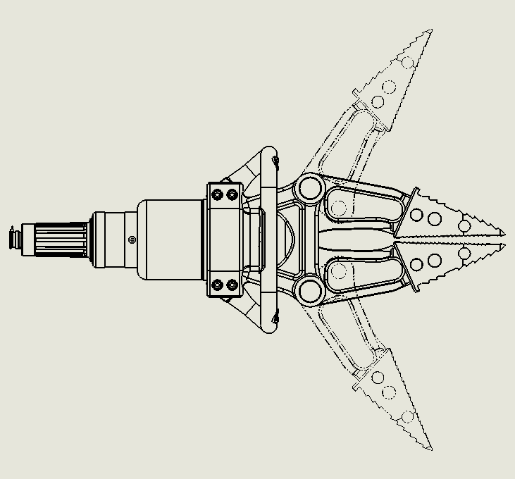
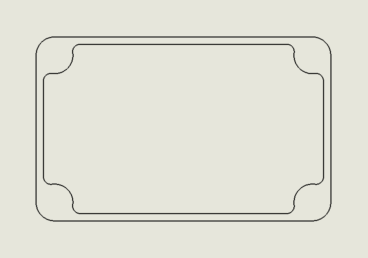
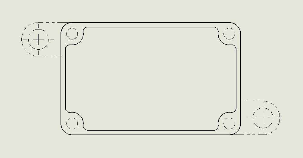
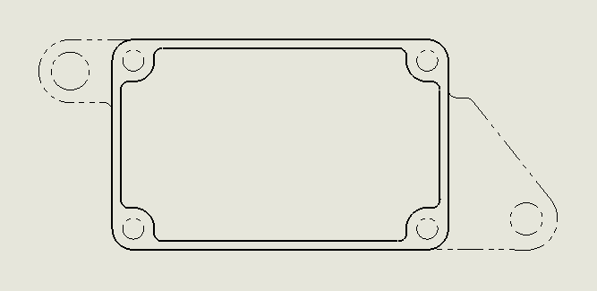
From the 2020 release Alternate Position Views can now be used for part views. They allow users to overlay two configurations of a part in one single view. The two configurations must already exist inside of the part before the alternate view is created.
This tool is useful for showing different versions of the same part together. For example, you might purchase standard parts, and then machine them. You can create a drawing view of the as-machined configuration, and then add an alternate position view to show the as-purchased configuration.
To add an Alternate Position View, ensure an existing view is already in the drawing.
Click Alternate Position View from the Drawing toolbar. Select the drawing view you wish to use.
In the Property manager choose the existing configuration you wish to overlay. Note: the configuration must already exist inside of the part file. The alternate view will be illustrated using Phantom lines.
To edit the configuration of the Alternate Position View, right click on the Alternate Position view inside of the drawing view. Click Edit Feature.
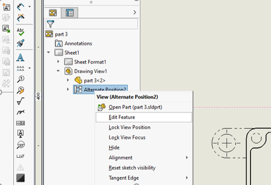
Choose the correct configuration from the drop-down list. The updated view should appear after refreshing.
TECH TIP
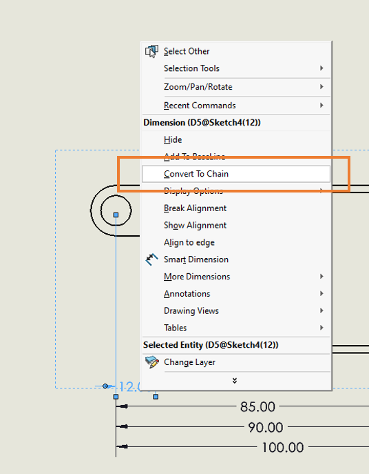
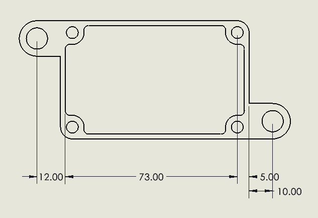
In SOLIDWORKS 2020, users are now able to convert baseline dimensions to chain dimensions and vise versa. P
To change a baseline dimension to a chain dimension, right click and choose Convert to Chain.