
Sketch Dimension Tool Tips
Every user of SOLIDWORKS is familiar with the Smart Dimension tool with which they can dimension both 2D and 3D sketches – where the type of dimension produced will be determined by the sketch entities selected. The following tips show some useful dimensions that are not commonly used within the Smart Dimension tool.
-
An arc angle dimension
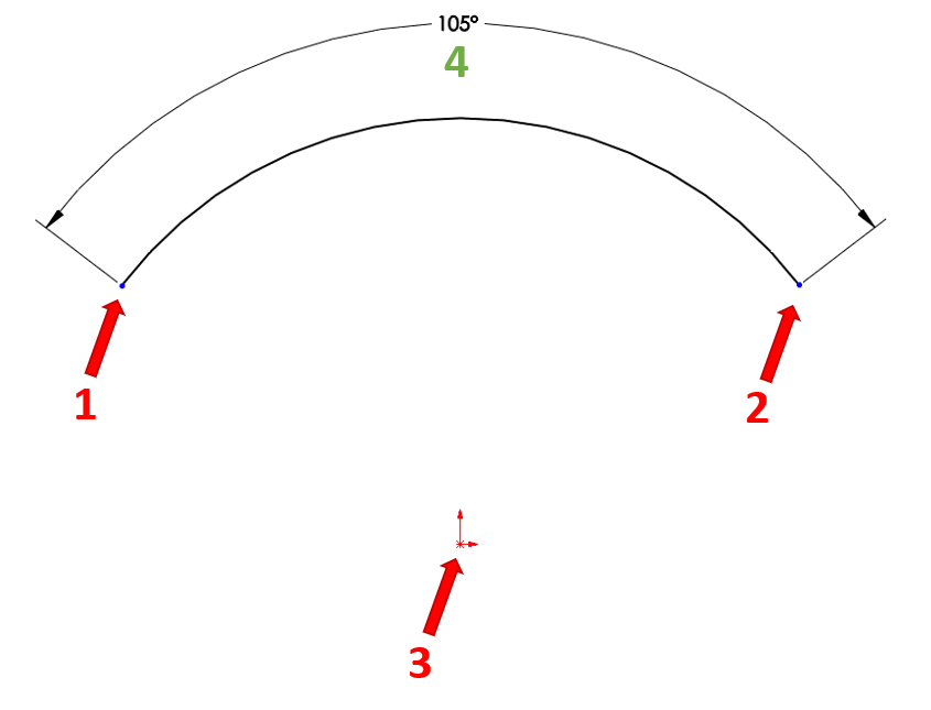
Using the Smart Dimension tool, it is simple to get the angle between 2 pieces of straight geometry. Many users are unsure how to achieve an arc angle without adding additional straight construction geometry. However, it is possible to dimension up the angle of an arc using just an arc’s three known points.
- With the smart dimension tool active, select the first arc end point.
- Then select the other end point of the arc.
- Select the arc centre point.
- You are now free to place the dimension.
-
An arc length dimension
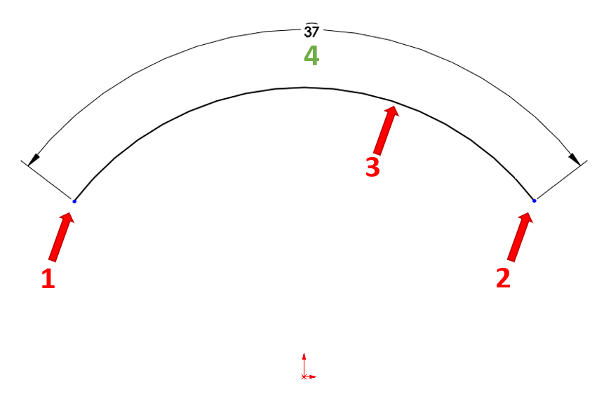
The default option for dimensioning an arc is a radius. As an alternative option, you are also able to easily show the length of an arc.
- With the smart dimension tool active, select the first arc end point.
- Select the other end point of the arc.
- Select the arc geometry.
- You are now free to place the dimension.
-
Dimensioning tangent to outside of an arc or a circle
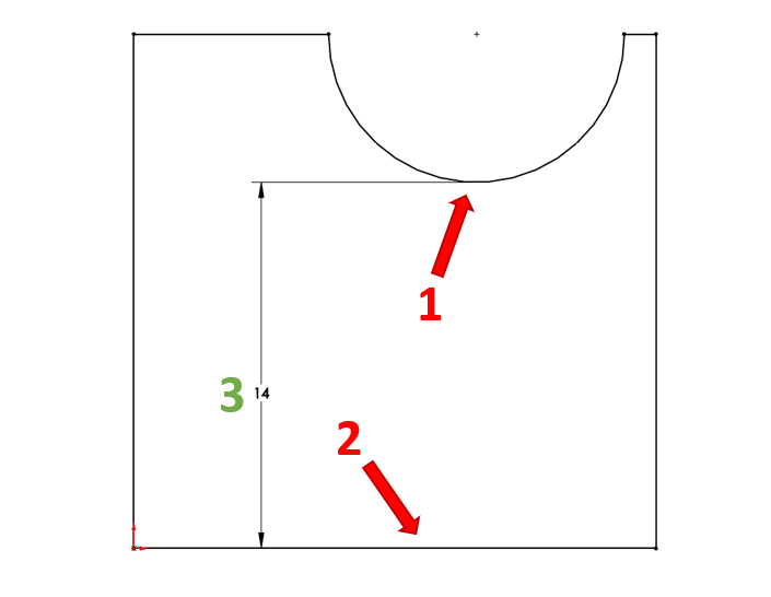
If you choose an arc or a circle for dimensioning, the default location that SOLIDWORKS takes the dimension from is the centre point. However sometimes you need to place a dimension tangent to the outside of the circle or arc. You can do this by utilising the Shift-key.
- With the smart dimension tool active, hold down the Shift-key and select the circle geometry.
- Select the other piece of geometry (no need to hold down the Shift-key if the geometry is straight. If the next entity is also a circle or an arc, continue to hold the Shift-key down).
- Place the dimension as you wish.
-
Dimensioning to the virtual sharp
A virtual sharp is the point that exists where two edges, lines, arcs, and/or curves would intersect if those entities were extended. Using the Smart Dimension tool and Find Intersection option, you are able to easily create a dimension to the virtual sharp of a sketch.
- With the smart dimension tool active, right-click on the first sketch entity.
- Select Find Intersection from the menu.
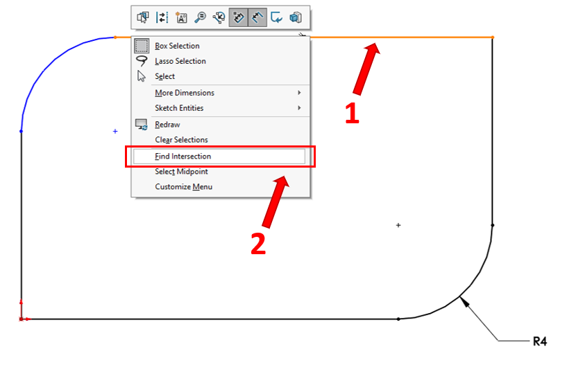
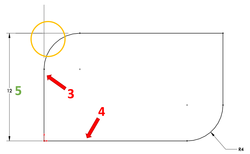
- Select the second sketch entity (with which the first one could intersect). At this point the virtual sharp should be created and the first dimension line will be attached.
- Select the second entity of the dimension. Alternatively, you can choose to repeat the steps by right-clicking on it, which starts the creation of a second vertical sharp. After choosing Find Intersection and selecting a second sketch entity, the second dimension line should be attached.
- You are then free to place the dimension.
-
Dimensioning symmetrical about a centreline
In a sketch with a centreline and additional line or point entities, you are able to dimension symmetrical to the centreline. This is useful when creating sketches for revolve features.
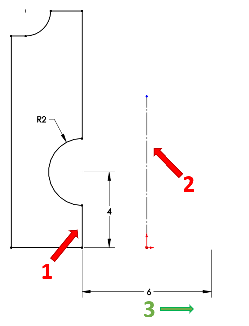
- With the smart dimension tool active, select the line to dimension.
- Select the centreline of the sketch.
- To place the dimension, drag it to the opposite side of the centreline.
-
Angle dimension with one entity
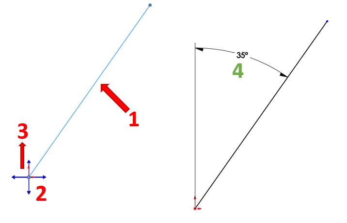
Many users would think that they may need an additional piece of construction geometry to be able to set the angle of a line entity. However, it is possible to take a dimension using an ‘imaginary line’ as reference to save on sketching time.
- With the smart dimension tool active, select the line to dimension.
- Select the line end point.
- A set of arrows should appear. Select the arrow in the direction that you wish to place the dimension.
- You are then free to place the dimension.